
PLANTS / SYSTEMS / INFRASTRUCTURE
3D Visualization for Industrial Facilities and Plants
Industrial plant rendering and 3D visualization show the complete facility—from outside, inside and in section. We connect the territory, buildings, utilities and technology in one controlled digital scene.
A drone shows the factory roof. 3D shows what happens underneath it.Discuss the project
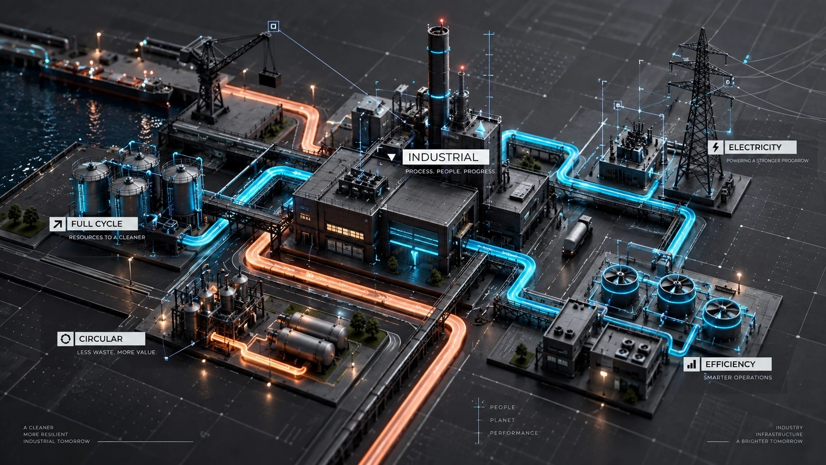
01 / BEFORE CONSTRUCTION
Show the facility before construction
Turn plans into a clear presentation of the future facility — for investors, tenders and project approvals.
02 / WHY CONTROLLED 3D
One object. Three very different ways to show it.
Photography and drone
Show what already exists and what the camera can physically reach.
OUTSIDEGenerative AI
Creates concepts quickly, but cannot guarantee the real layout, dimensions or process logic.
CONCEPTTechnical 3D scene
Keeps the facility consistent across every image, cutaway and animation.
CONTROLAI can invent a beautiful factory. Our task is to show yours.
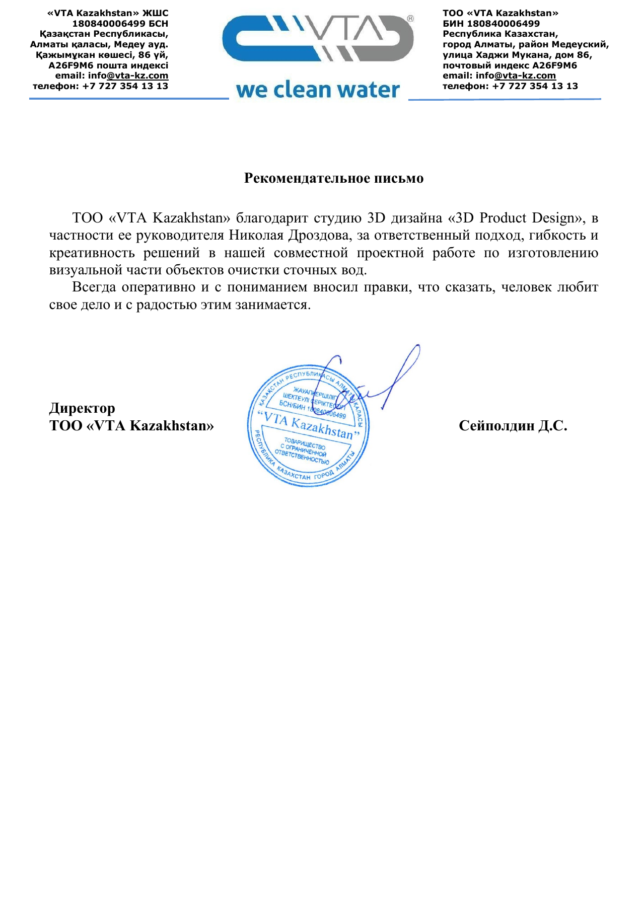
CLIENT RECOMMENDATION / VTA KAZAKHSTAN
A Kazakhstan client. A wastewater treatment project in Dubai.
The visualization was created for VTA Kazakhstan in connection with a wastewater treatment facility project in Dubai. The client is based in Kazakhstan and issued its recommendation letter in Russian. A short English summary is provided below; the signed original is available as a PDF.
SUMMARY OF THE LETTER
VTA Kazakhstan thanks 3D Product Design and its director, Nikolai Drozdov, for a responsible approach, flexibility and creative solutions in their joint work on wastewater treatment facility visuals. The company highlights prompt, attentive handling of revisions and genuine enthusiasm for the work.
03 / FACILITY SCALE
Huge sites require a different scale of visualization
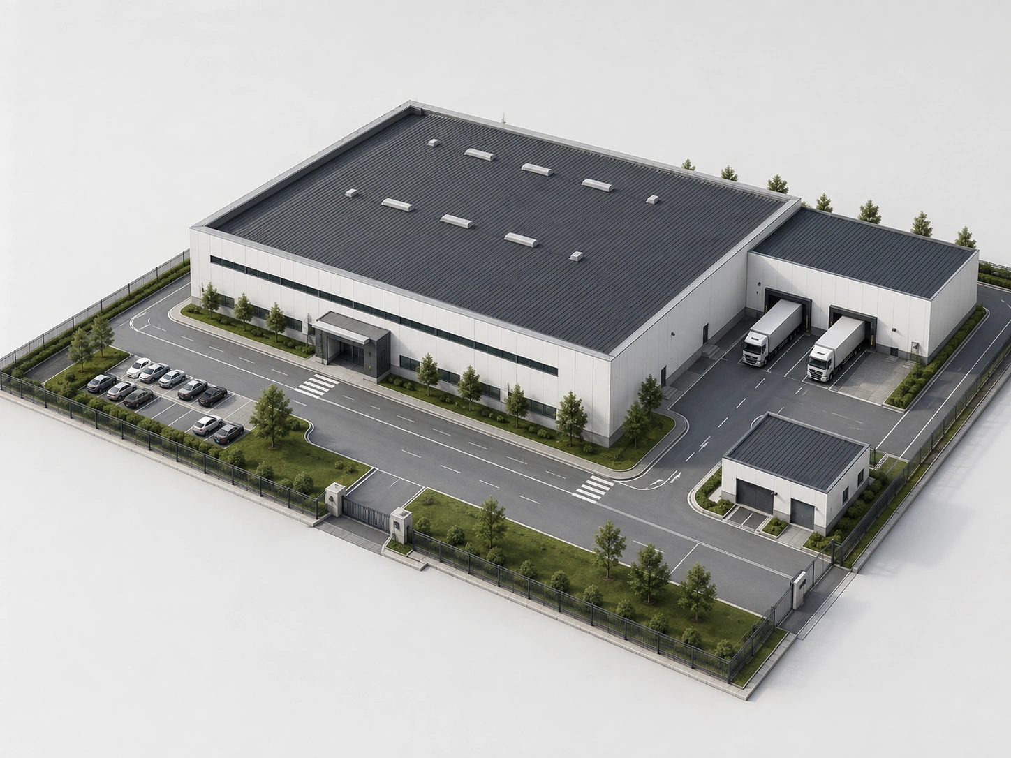
A single industrial site can contain hectares of territory, many buildings, production zones, pipelines and engineering systems.
04 / SITE OVERVIEW
A master view that actually explains the facility
Show boundaries, buildings, roads, loading areas, transport, logistics, utilities and future expansion on one understandable image.
- Understand the scale immediately
- See how every zone is connected
- Compare current and future stages
05 / CUTAWAY
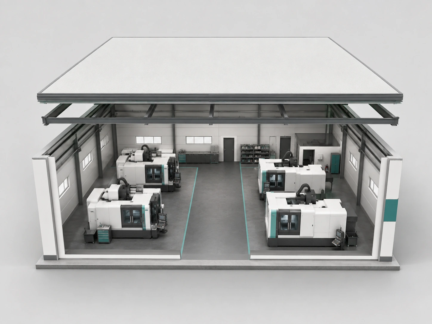
Remove the roof. Make the walls transparent.
The important information is often inside. A single scene can show a whole-building cutaway, isolated floors, equipment placement, transparent structures and an exploded view.
If the required camera angle is inside a wall, sending a drone there is a bad idea. In 3D the wall simply becomes transparent.
06 / ENGINEERING SYSTEMS
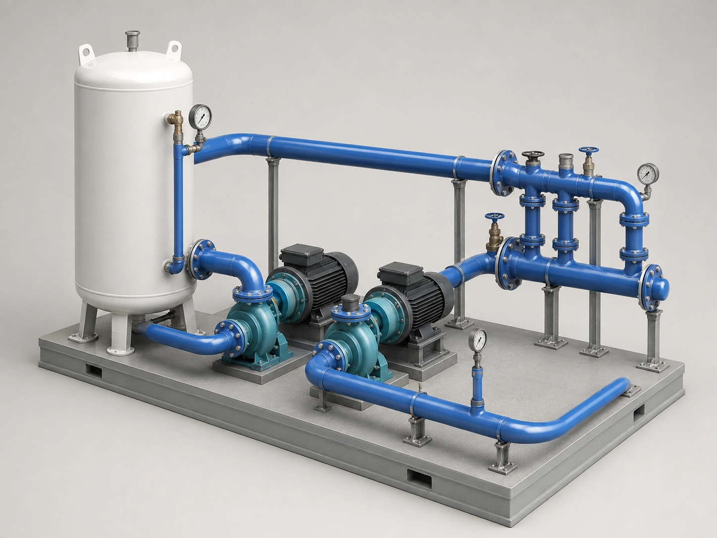
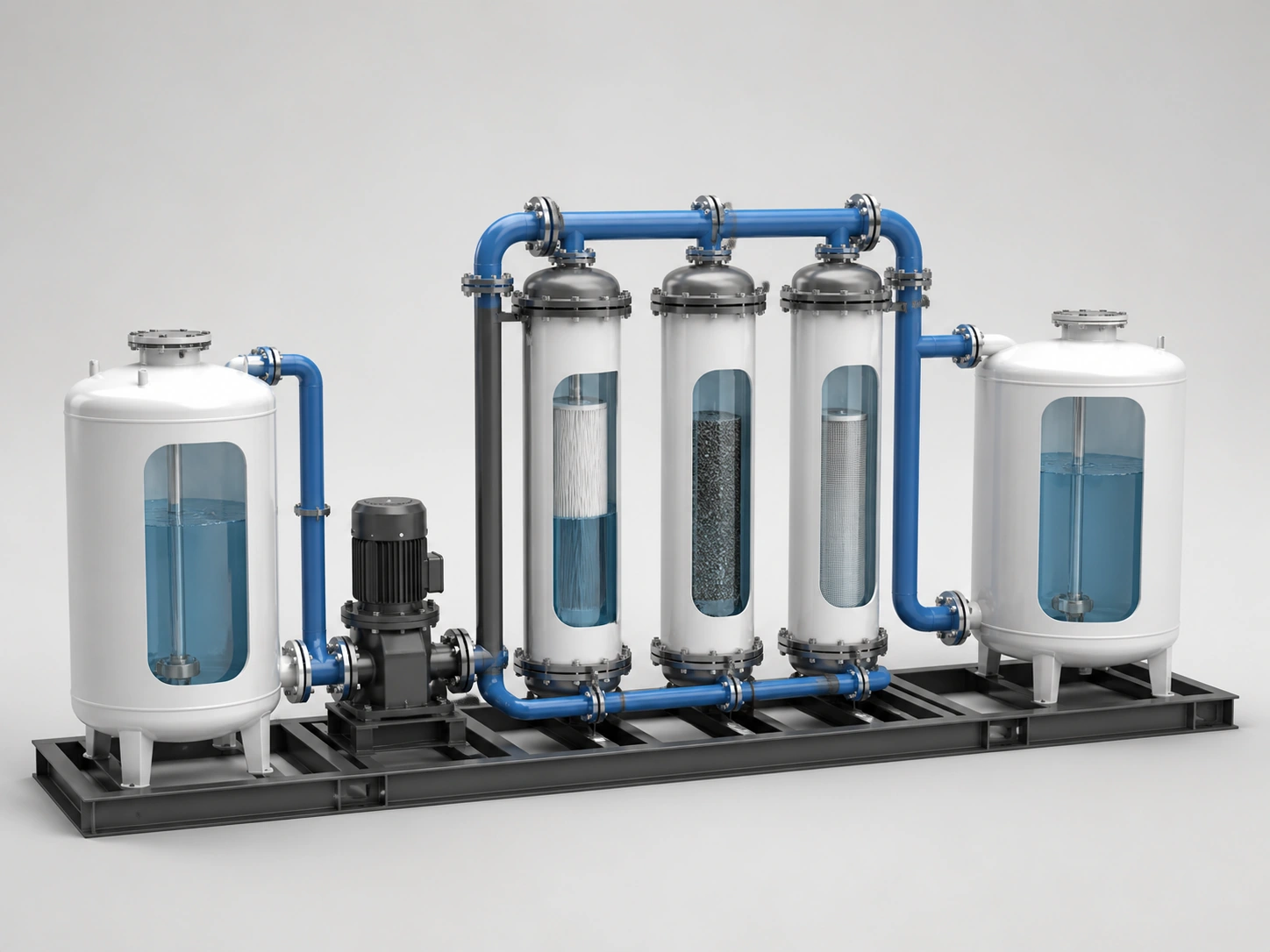
Follow every utility from beginning to end
Color coding and isolation make hidden infrastructure easier to understand than a photograph of a crowded workshop.
07 / PROCESS ANIMATION
Show how the technology works
Motion, color and labels guide the viewer through raw material intake, conveyors, filtration, heating, cooling, fluid circulation, energy transfer and finished output.
08 / ONE CONTINUOUS STORY
From the complete site to the mechanism inside a machine
One presentation connects every level, so the client does not need to assemble the story from plans, photos and technical descriptions.
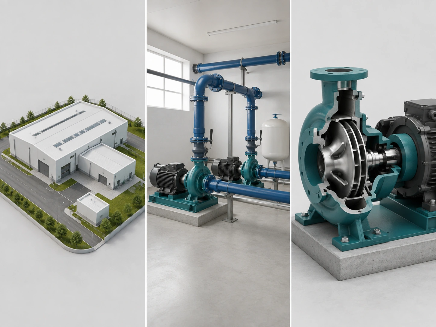
- 01Territory
- 02Building
- 03Production line
- 04Equipment
- 05Mechanism
- 06Operating principle
09 / ONE SCENE
One facility becomes many visual materials
Open the scene again whenever a new angle, format or communication task appears.
10 / FACILITY EVOLUTION
Update one part—not the entire visualization
Built another workshop? Add it to the scene instead of asking a satellite to reshoot the entire territory.
- Update the building
- Replace or add equipment
- Correct the utilities
- Render new materials
11 / FACILITY TYPES
Built for complex industrial environments
12 / SOURCE MATERIALS
Start with the materials you have
Send a plan, a model or photos and tell us what the presentation needs to explain. We will review the available information and identify what else is needed.
Plans and reference photos can be a starting point. The detail level depends on the source information we can verify together.
For an estimate: materials + task + desired deadline.
3D models
CAD / BIMThe equipment and building geometry available for the project.
Plans and drawings
SITE / FLOORS / SECTIONSSite boundaries, dimensions, room layouts and equipment positions.
Systems and technology
UTILITIES / PROCESSUtility diagrams and a description of how the production process works.
Photos and site references
PHOTO / VIDEO / DRONE / MAPSReference views of the site, equipment, finishes and surroundings.
13 / WORKFLOW
Work stages: from STEP file to visualization
01 / MODEL PREPARATION
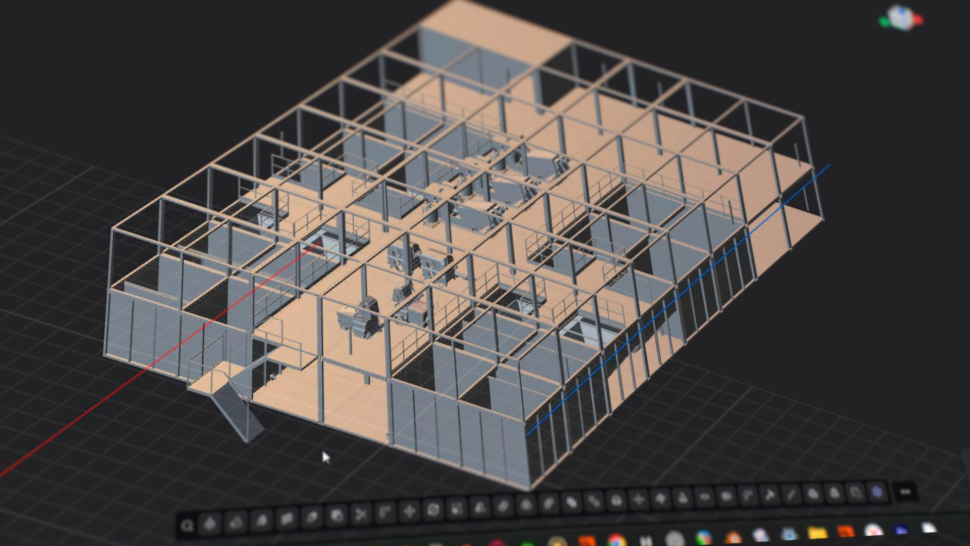
Prepare the STEP model for the shots that matter
First, I prepare your STEP file according to the brief: the required views, close-ups and processes to demonstrate. In this example, I organize the model by levels and object groups, combine related elements and refine the geometry needed for visualization.
Engineering models are often simplified and may omit details that become noticeable in a render. I refine the areas that will be clearly visible in close-ups or used for water and process simulations. The level of detail follows the brief, with missing technical information clarified with the client.
- 02
Choose the presentation
Plan cameras, cutaways, colors and demonstration sequence.
- 03
Set up materials and motion
Prepare surfaces, lighting and any process animation or simulations required by the brief.
- 04
Produce the materials
Render images, diagrams, animation and additional formats.
- 05
Preserve for updates
Reuse the digital facility in future presentations and campaigns.

RELATED PROJECT / SUECO
Water treatment in Dubai
See how 3D visualization and explanatory animation present the facility layout, filtration equipment and treatment stages.
View project14 / FAQ
FAQ
What can industrial facility visualization show?
The complete site, buildings, interiors, equipment, utilities, process flow, underground infrastructure and individual mechanisms.
Can the facility be visualized before construction?
Yes. We can build the scene from CAD, BIM, drawings, site plans and approved engineering information.
Can the model be updated later?
Yes. Buildings, equipment and utilities can be changed without rebuilding the entire scene.
MAKE THE WHOLE SYSTEM VISIBLE
Show the facility as it cannot be seen in reality
We show not only how an industrial facility looks, but how it is built, works and develops.