Loader visualization

RBF03ULTRA

3D modeling and product visualization

Project brief

The RBF03 Ultra project is a detailed look at my workflow and what working with me involves. On this page, I explain which materials I need from you and walk through the process step by step: from references and modeling to materials, lighting, approval and delivery of the finished visualization.

Explore the workflow
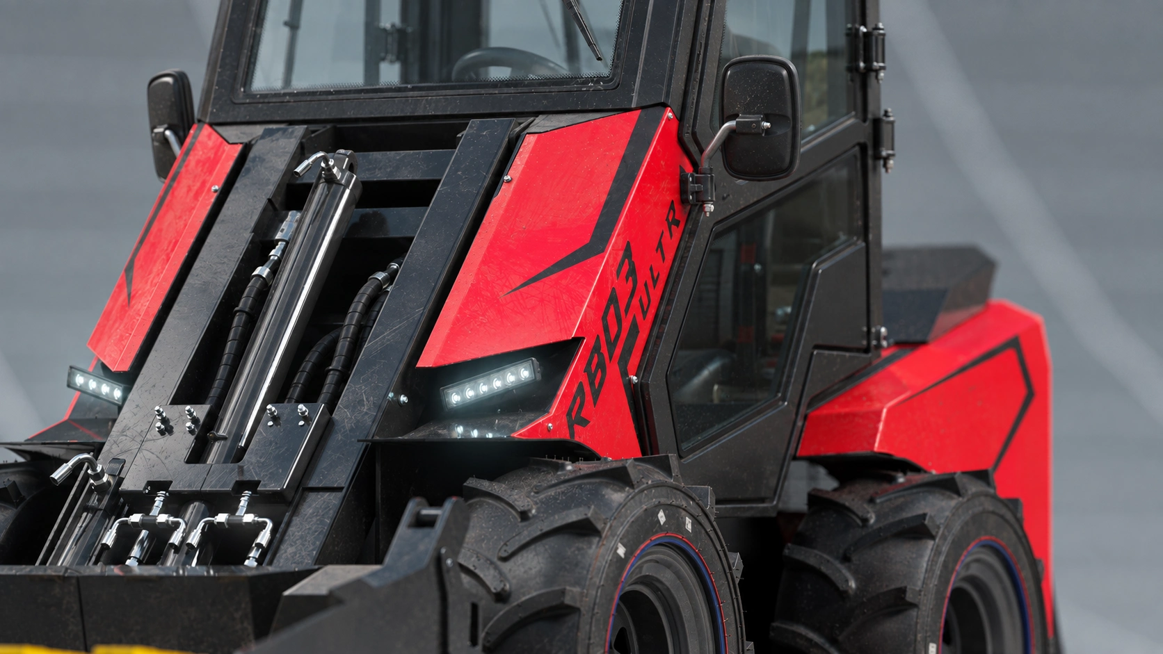
RBF03 ULTRA
The full process, step by stepI explain every stage in detail, from the first reference materials to the finished visualization.
Source materials and pricingI explain in detail which photographs, views and dimensions are needed, how working with or without a CAD model differs, and how visualization pricing is determined.
How we work togetherHow I build the model, agree on materials, lighting and views with you, make revisions and deliver the final files.
01

The client problem

Prepare an entire equipment range for a website configurator, with consistent camera angles, lighting and scale so customers can compare machines, not differences in presentation. The models also needed to support future equipment updates. RBF03 Ultra was built entirely from scratch using photographs as the only reference — not an existing 3D model.

02

My solution

I reconstructed the shape, proportions and visible components from photographs. The approach brings RBF03 Ultra into a shared visual system: consistent cameras, lighting and materials across the range. The aim is to update individual components and configurations while preserving the overall presentation — making the 3D model a reusable asset as the product evolves.
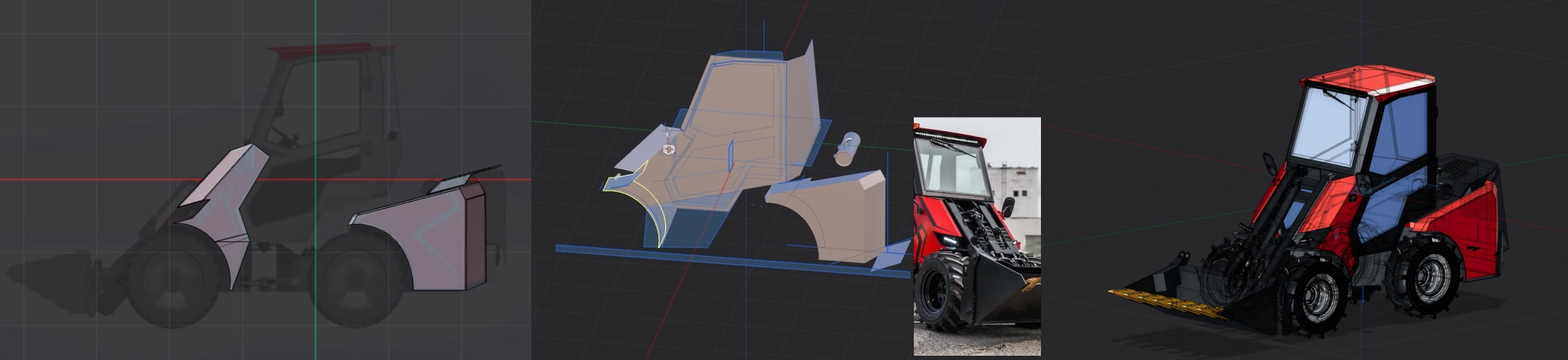
RBF03 Ultra modeling stages: beginning, 20% and 70% of the work
  1. Beginning of work
  2. 20% of the work
  3. 70% of the work

How the model evolved

The full workflow will be shown in a video in the section below.

Not an adaptation of a ready-made asset: I built this model from the ground up, reconstructing the loader’s shape and visible details from photographic references.

Images of three stages are included here to show how the model evolved as details were added.

SOURCE MATERIALS / TWO WAYS TO START

Your engineering know-how can stay with you.

Clients are often reluctant to share an engineering model — and I understand why. For exterior visualization, I do not need the internal design. You can remove the engineering internals and send only the outer geometry. If sharing even that is not an option, we can work from photographs.

01 / WITH AN ENGINEERING MODEL

Starting roughly halfway there

A CAD model gives me the proportions and main geometry: I can start at roughly 50% of the modeling work rather than from zero. It is not yet a render-ready model. Visually, engineering geometry is often simplified: I prepare and combine elements, refine bevels, edges and joints, and add missing visible details. Then come materials, lighting and rendering.

What to send: an exterior-only model and photos of the actual product. The 50% figure is a starting-point estimate, not a fixed discount or a promise that half the entire project is complete.

What I do after receiving the model

  1. Organize the model. Group components into assemblies and clean up the model structure.
  2. Compare it with the real product. Check the construction and appearance against current photographs of the machine.
  3. Prepare the geometry. Refine body panels and joints for weld seams and join elements for visualization.
  4. Add details. Model missing visible components and refine bevels, edges and fasteners.
  5. Model the wheels. Develop tire shapes, tread, rims and wheel fitment.
  6. Add weld seams. Recreate seams along the body and joints based on the actual product.
  7. Assemble the visualization scene. Move the prepared model into another application and assemble the rendering scene.
  8. Set up lighting. Light the scene to reveal the shape, volume and important machine details.
  9. Create materials. Develop paint, metal, rubber and glass based on the real surfaces.
  10. Choose effective camera angles. Select views that showcase the product and suit the website or catalog.
  11. Send previews for approval. Share preliminary images to agree on materials, lighting and camera angles together.
  12. Complete the entire range. After approval and revisions, develop the full equipment series in one consistent style for the website or catalogs.
  13. Deliver the finished materials. Compile and hand over the complete agreed set of files for further use.

02 / WITHOUT AN ENGINEERING MODEL

Rebuilding the exterior from photos

The engineering model stays with you. I reconstruct the visible shape and details from photographs — as I did with RBF03 Ultra. This requires more reference photos than working from CAD: all sides, top views where possible, and close-ups of connections, surfaces and small components.

The first step: four main screenshots instead of sharing the model. If you have an engineering model but prefer not to send the file, I first ask your engineer to open it in their software and capture left, right, front and rear views. I may also request a top view if needed. Ideally, use standard views without perspective distortion and show the entire machine. These help establish its shape and proportions; photographs of the real product are still needed to clarify details and materials. There is no need to share the model file or internal construction. If no engineering model exists, we start with photographs and overall dimensions.

It is rarely possible to gather every reference photo at the start. As I build the model, new questions about shapes, connections and proportions emerge, so I request additional views in stages. Alongside modeling, I carefully compare the photographs and review videos of the specific product on your YouTube channel, when available, to understand geometry that a single image cannot reveal.

In my experience, studying the product, comparing references and clarifying the geometry accounts for around 35% of the time spent working from photographs. This is part of the work needed to reconstruct your actual product accurately, rather than create something that merely looks similar.

Modeling from scratch increases the price by 50% compared with working from a supplied engineering model, for the same scope of visualization.

What to send: a comprehensive photo set and overall dimensions. I will identify any missing views and explain what else to photograph. Internal engineering data is not needed for exterior visualization.

RBF03 ULTRA / PHOTO COMPARISON

Modeling accuracy from photographs

I compare the 3D model with a photograph of the real machine, checking the silhouette, cab and body proportions, wheel positions and visible details. This comparison helps reveal differences and progressively bring the model’s appearance closer to the actual product.

* A different bucket was modeled here, not the one shown in the photograph.
Comparison of the RBF03 Ultra loader 3D model with a photograph of the real machine

RBF03 ULTRA / SOURCE MATERIALS

This many photographs are enough for visualization.

I used the photographs collected in the collage below for this project. This is what a working reference set looks like: overall machine views, close-ups and engineering model screenshots. Together, they help me reconstruct the product accurately.
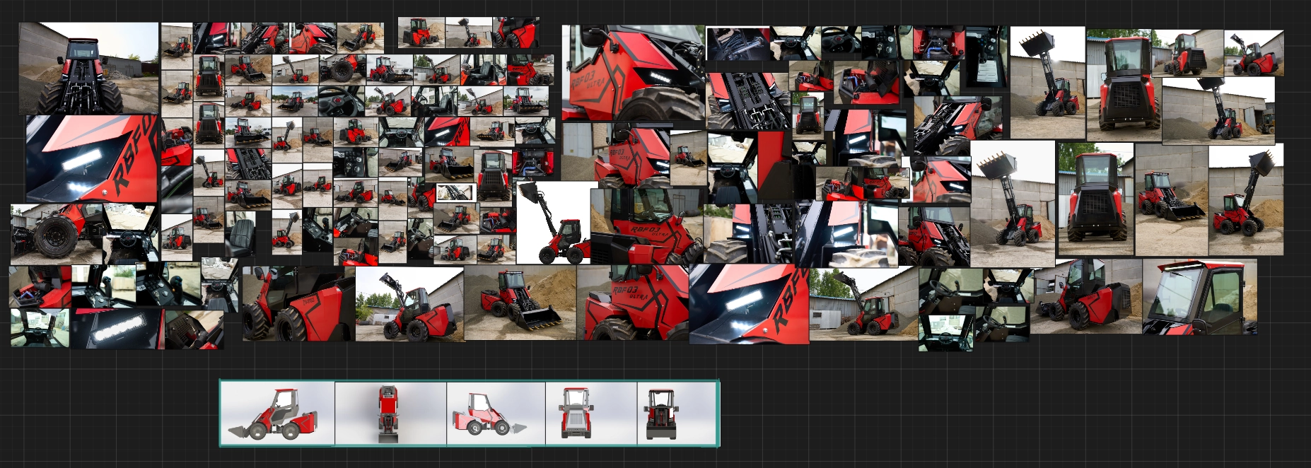
RBF03 Ultra reference board: photographs of the machine and details, with engineering model views along the bottom
Actual reference materials for the RBF03 Ultra project. Click the collage to open it at full size.

I first request four main views: left, right, front and rear. Notice the row of model views at the bottom of the collage: these establish proportions, the silhouette and the relative positions of components. We add a top view and other angles when needed.

It is rare to receive every necessary angle at the start. In my experience, I add around 50% of the working reference images during the project, extracting useful frames from videos of the specific product on the client’s YouTube channel. To avoid interrupting you with every new question, I first review publicly available materials myself: the website, photographs, reviews and machine demonstrations. If a detail still cannot be seen clearly, I request a specific additional photo.

An engineering model often differs visually from the finished machine: panels, fasteners, equipment and small details can change during production. That is why I usually ask for the most recent photographs of the specific machine. I check geometry against the main views and visible details against current photos, so the visualization shows the latest product version rather than an outdated design.

RBF03 ULTRA / FULL PROCESS

From photographs to a finished 3D model.

This video shows the complete process of building the machine from photographs: how the reference materials become a loader model, step by step. Follow the sequence of work and see the attention given to each component.

The recording is sped up 3.5× to make the full process easier to watch.

Watch on YouTube

ORDER SIZE / COST PER MACHINE

One visual setup for an entire equipment range.

For a single machine, I prepare the complete setup: bodywork, metal, rubber and glass materials, the environment, lighting and camera angles. That preparation is included in the visualization cost of one product.

With five machines presented in the same style, I do not need to repeat the entire setup five times. I reuse a shared material library, environment and agreed lighting scheme, adapting them to each model. The common preparation cost is spread across the series, bringing the cost per machine below five separate commissions built from scratch.

Each machine still needs individual work on geometry, unique details and final images. Savings depend on the similarity of the machines, the number of views and a consistent visual style, not just the quantity. The more we can reuse, the more economical the series becomes — without reducing quality.

Share the materials you are comfortable sharing — I will suggest a practical way to build the visualization.

RBF03 ULTRA / 02

Construction and details

Close-ups focus on selected components and their relationship to the complete machine.

Project image will be added
RBF03 ULTRA / Tire detail

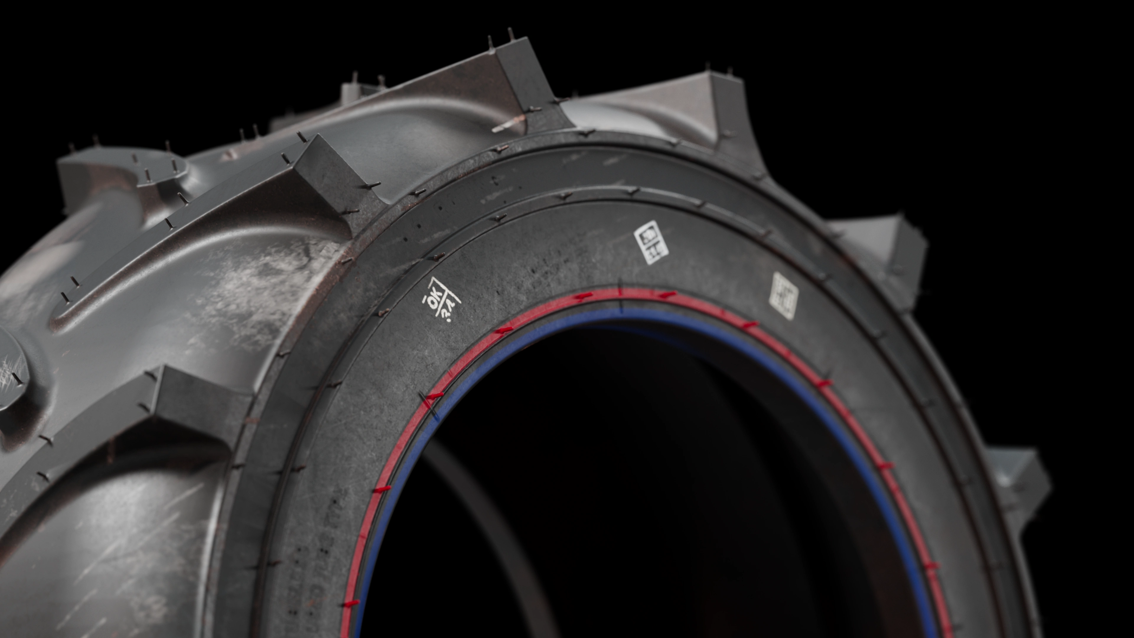
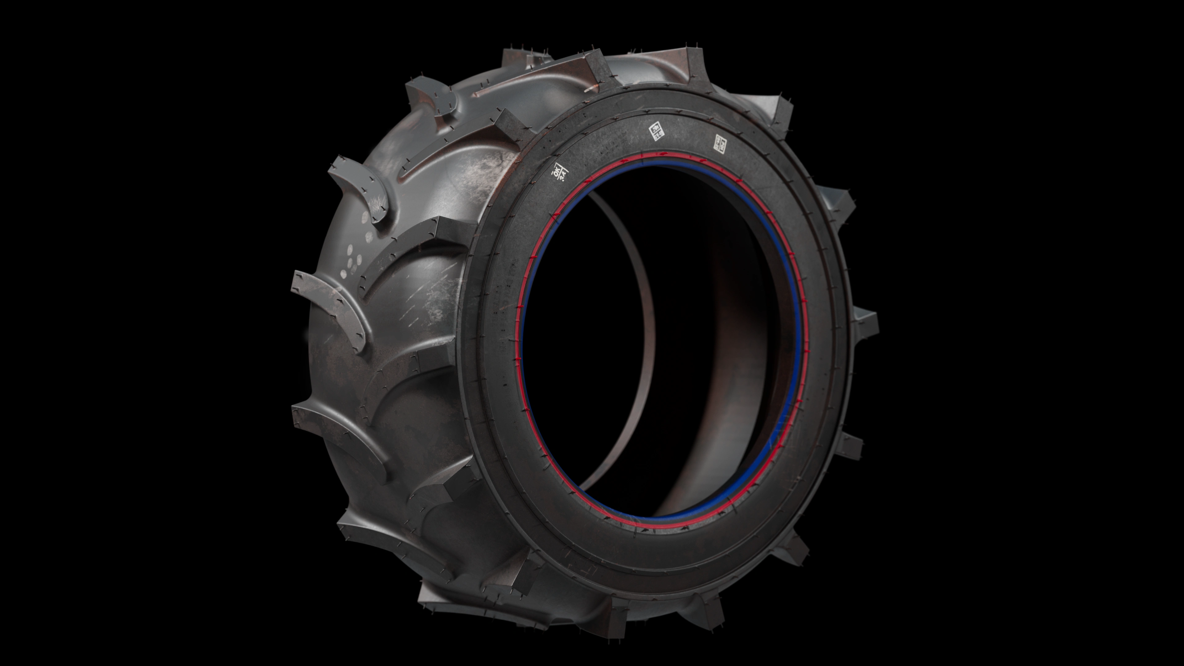
A custom tire. Down to the smallest detail.

This tire was modeled and textured specifically for the client. Every fine rubber whisker was individually crafted by hand, giving close-up views the same attention as the complete loader.

Even the painted stamps on the rubber were recreated in the textures.

Watch on YouTube

RBF03 ULTRA / 03

Materials and final views

Consistent lighting and surface presentation bring the product images into one visual series.

Project image will be added

03

Project materials

A reusable visual system, not a single image.

01

3D model

Geometry based on the project references.

02

Product renders

Overall views with consistent lighting and materials.

03

Detail views

Close-ups of selected construction elements.

04

Website and catalog materials

Presentation formats selected for each publication channel.

Presentation goal

A consistent presentation of RBF03 Ultra

The presentation is designed to connect overall views and close-ups in one visual style. Final images and confirmed project results will be added with the project materials.

RBF03 ULTRA / FROM REFERENCES TO RESULTS

Ready to show your machinery in detail?

Send photographs or an engineering model. I will review the materials, suggest a visualization approach and estimate the project cost.

YOUR PRODUCT. CLEARLY PRESENTED.